Hey Siri, Grind me a Double
-
Comments:
- here.
We have a spare coffee grinder at work: it’s the same model I have at home, a Sunbeam Cafe Series EM0480. They are a pretty good coffee grinder: you can get them for around $200 or less, and with the conical burrs, they grind a nice consistency of coffee.
The one at work is somewhat surplus: it was the one we were using at the office, but it needs a new spacer because it will not grind fine enough to make a decent cup of coffee. I’ve been meaning to get one from eBay (I’ve had to do that to two other grinders).
So, I bought it home to attempt to hack in a timer circuit, so I could trigger it to grind for 11 or 16 seconds: the amount of time I normally count in my head when grinding a single or a double. It would be even better to have it weight based, and I even have some load sensor ICs coming, but I’m still not exactly how I’ll mount the actual load cell(s).
In the meantime, I bought an Arlec Grid Connect socket from Bunnings today. It’s just a pass-through, but can switch on/off automatically. And, importantly, like the plug I re-flashed the other week, it runs Tuya, so can be flashed without having to pull it to bits.
There is a bit of trial-and-error when doing that though: not with the actual flashing, but with determining which GPIO pins connect to which switch(es), or lights/relays.
I used a temporary firmware to help make that simpler:
substitutions:
  device_name: test_rig

wifi:
  ssid: !secret ssid
  password: !secret password

  ap:
    ssid: ${device_name}_fallback
    password: !secret password

captive_portal:

esphome:
  name: $device_name
  platform: ESP8266
  board: esp01_1m

binary_sensor:
  - platform: status
    name: "Status"

  - platform: gpio
    pin:
      number: GPIO0
      inverted: true
      mode: INPUT_PULLUP
    name: GPIO0

  - platform: gpio
    pin:
      number: GPIO1
      inverted: true
      mode: INPUT_PULLUP
    name: GPIO1

  - platform: gpio
    pin:
      number: GPIO2
      inverted: true
      mode: INPUT_PULLUP
    name: GPIO2

  - platform: gpio
    pin:
      number: GPIO3
      inverted: true
      mode: INPUT_PULLUP
    name: GPIO3

  - platform: gpio
    pin:
      number: GPIO4
      inverted: true
      mode: INPUT_PULLUP
    name: GPIO4

  - platform: gpio
    pin:
      number: GPIO5
      inverted: true
      mode: INPUT_PULLUP
    name: GPIO5

  - platform: gpio
    pin:
      number: GPIO12
      inverted: true
      mode: INPUT_PULLUP
    name: GPIO12

  - platform: gpio
    pin:
      number: GPIO13
      inverted: true
      mode: INPUT_PULLUP
    name: GPIO13

  - platform: gpio
    pin:
      number: GPIO14
      inverted: true
      mode: INPUT_PULLUP
    name: GPIO14

  - platform: gpio
    pin:
      number: GPIO15
      inverted: true
      mode: INPUT_PULLUP
    name: GPIO15

  - platform: gpio
    pin:
      number: GPIO16
      inverted: true
      mode: INPUT_PULLUP
    name: GPIO16

sensor:
  - platform: wifi_signal
    name: "WiFi signal sensor"
    update_interval: 60s

ota:

logger:

mqtt:
  broker: "mqtt.lan"
  discovery: false
  topic_prefix: esphome/${device_name}
You can flash the firmware.bin this config file generates, and then press each button, taking note of which one is connected to which GPIO pin.
Then, phase 2 is to see which GPIO pins are connected to the LED(s) and/or relays. I’ve generally still been doing that one by one, because there’s no real other convenient way to do it. You could have something that turns each one on and then off one after another, but that’s a bit tricky in esphome.
Anyway, in the case of this socket, the red LED is connected to GPIO13, the blue LED to GPIO4, and the relay to GPIO14.
My base esphome config file for this device looks like:
esphome:
  name: $device_name
  platform: ESP8266
  board: esp01_1m

binary_sensor:
  - platform: status
    name: "Status"

  - platform: gpio
    pin:
      number: GPIO14
      inverted: true
      mode: INPUT_PULLUP
    name: GPIO14
    on_press:
      - switch.toggle: relay

switch:
  - platform: gpio
    id: relay
    pin: GPIO12
    on_turn_on:
      - light.turn_on: red_led
      - light.turn_off: blue_led
      - mqtt.publish:
          topic: HomeKit/${device_name}/Switch/On
          retain: ON
          payload: 1
    on_turn_off:
      - light.turn_off: red_led
      - light.turn_on: blue_led
      - mqtt.publish:
         topic: HomeKit/${device_name}/Switch/On
         retain: ON
         payload: 0

light:
  - platform: binary
    output: led1
    id: red_led
    restore_mode: ALWAYS_OFF
  - platform: binary
    output: led2
    id: blue_led
    restore_mode: ALWAYS_ON

output:
  - platform: gpio
    pin:
      number: GPIO4
    id: led2
    inverted: True
  - platform: gpio
    pin:
      number: GPIO13
    id: led1
    inverted: True

sensor:
  - platform: wifi_signal
    name: "WiFi signal sensor"
    update_interval: 5min

ota:

logger:

mqtt:
  broker: "mqtt.lan"
  discovery: false
  topic_prefix: esphome/${device_name}
  on_message:
    - topic: HomeKit/${device_name}/Switch/On
      payload: "1"
      then:
        - switch.turn_on:
            id: relay
    - topic: HomeKit/${device_name}/Switch/On
      payload: "0"
      then:
        - switch.turn_off:
            id: relay
  birth_message:
    topic: HomeKit/${device_name}/Switch/On
    payload: "0"
  # will_message:
  #   topic: HomeKit/${device_name}/Switch/On
  #   payload: "N/A"
This includes the stuff to hook it up correctly to MQTT2HomeKit, which I’m now going to extend to it will hopefully correctly flag an accessory as “Not Available”.
But, that is only half of the puzzle. We still need some way to have the switch turn on, and then after a short period of time, turn off. It’s not possible to do this in HomeKit: you can have some other trigger turn on a Switch, and then turn it off after an integral number of minutes, but you can’t trigger a device to turn itself off after it turns on, or do so after 16 seconds.
Enter Node-RED, and Siri Shortcuts.
Because I’m a little paranoid about this accidentally triggering, I wanted to ensure that it turns off after the maximum grind time, for me about 16 seconds.
I also wanted to be able to trigger either a short or a long grind time. I’ve taken the approach of using two different HTTP endpoints for these two, although it would be possible to pass the required on time in a single endpoint.
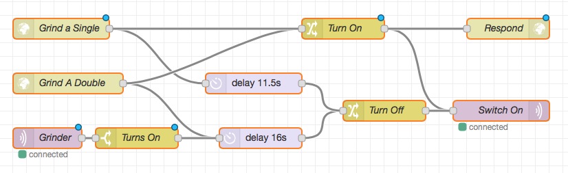
Each HTTP endpoint sends two messages: one to turn on the grinder, and the other to delay for the required period of time, and then turn off the grinder. Each of these messages passes through a node that sets the required payload, and then goes to the same MQTT output node. The “Turn On” message also goes to an HTTP Response output node. It took me a while to realise that this is required, otherwise the Siri Shortcut will wait until the request times out.
The bottom MQTT input node listens for the grinder to be switched on (which could happen by a manual press of the button, or otherwise turning it on in HomeKit), and then, after 16 seconds, turns it off. I’ve reused the same message flow, so that this timer will always be the same as the “Grind a Double” message. In practice, we could just have the “Grind a Double” turn it on, and then this sub-flow turn it off, but explicit is better than implicit.
So that just leaves the Siri Shortcut. That too is fairly straightforward: it just fires off an HTTP POST request to the correct endpoint:
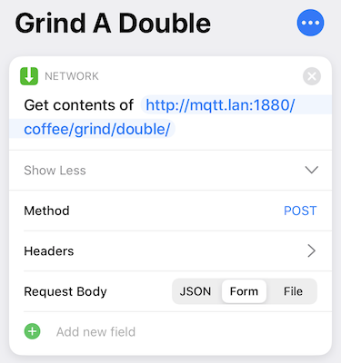
And the other one is just as simple.
Now, I’m off to make another coffee.
Hey Siri, Grind A Double!