Hacking the DETA rewireable plug
-
Comments:
- here.
There are a bunch of inexpensive IoT devices coming onto the market. One of these ranges are the GridConnect devices available from Bunnings. I’ve been eyeing these off, because they include some fairly reasonable looking switches and plugs, and, most importantly, are legal to have installed in your home in Australia.
I’m not okay with sticking a bunch of devices into my home network that communicate with the outside world. I like to use Apple’s HomeKit, which means the communication is funnelled through their systems, and everything I have configured as a HomeKit accessory either has no cloud component, and is where possible isolated onto a seperate wireless network.
In fact, most of my devices are home built, and have limited accesibility: they are permitted to connect to an MQTT server and nothing else.
Most of the commercially available items in Australia fail this test: they all have their own little cloud service. I dislike this for a couple of reasons: the first is security and privacy. I don’t trust that these providers will protect my data.
The second is a little more subtle: if an IoT provider goes out of business (or decides to end-of-life some products), then you are no longer able to access them in the way you might have liked.
So, I’ve been creating my own devices, or re-purposing commercial devices where possible. I grabbed a couple of the Mirabella globes, and was able to flash them with an ESPHome firmware, that I believe hardens the device somewhat. Having controllable light globes is neat, but realistically, they are of limited use. Having to use an App to turn on and off your lights is unacceptable, but also so is having an always listening microphone. And, again, what happens when you want to turn your lights on and your internet is down?
So, I’m more interested in smart switches.
I was not able to find much information about the Deta line of products that support GridConnect, so I went and bought the cheapest one, that I thought I was going to be realistically able to reverse engineer.
Opening up the “user accessible” region, we see the three screws for attaching the cable, and some lovely 2.0mm triangular screws.
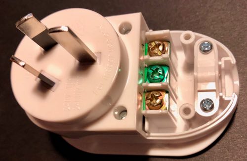
After spending more money on a set of screwdriver bits that had this size and shape, we are able to see the top of the PCB.
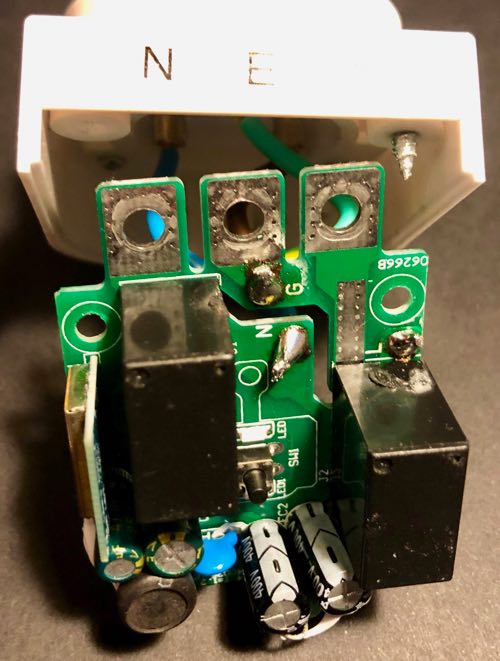
Note that there are two relays: this is safer than things like the Sonoff Basic, that only switch the active wire, rather than both.
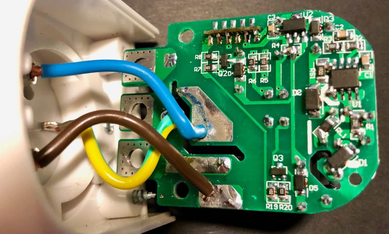
The underneath shows clearly the separation between the different AC lines.
Finally, we can see the brains behind this switch:
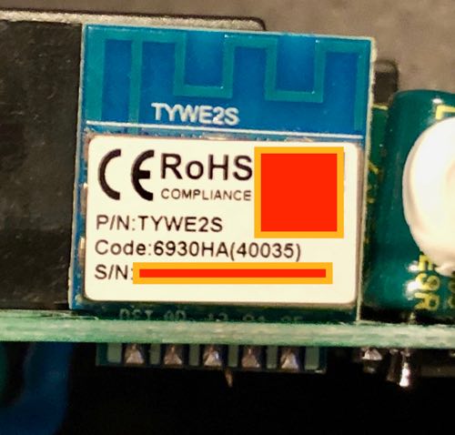
Note the code on the microcontroller: TYWE2S. Plugging that into a search engine yielded some interesting results.
It turns out that not only are these using an ESP8285 (which is just an ESP8266 with onboard flash, and in a smaller package), but they are running the Tuya firmware. So, it wasn’t even necessary to have opened up the casing.
Since I had a Raspberry Pi Zero W configured to run tuya-convert, I built up a simple firmware that would enable me to run OTA updates after flashing, and settled down to working out which GPIO pins are attached to which parts: the button, LED and relay.
(Oh, and this was interesting: both the active and neutral lines are toggled by relays, as opposed to something like the Sonoff, that only toggles the active line).
At some point, possibly because I was tired, I flashed a firmware that accessed GPIO pins 6 and 7. This locks the device up, and prevents booting. So, I then soldered some wires onto the device (after opening it back up again: so it turned out I did need that fancy screwdriver bit) to get access to the UART.
Interestingly, the ESPHome firmware detects that it’s been unable to boot, and boots into a safe mode. So, again, in hindsight, I still didn’t need to open it up.
Through trial and error, I was able to determine which GPIO was the button. That’s the easiest (and was helpful for me to be able to determine the LED and relay).
Surprisingly, it was GPIO1. Those familiar with the ESP8266 may know this is normally the TX pin for the UART. Which explains why, when I had the serial port connected, I was seeing a bunch of weird things when I pushed the button.
Once I had that, it was a matter of trying each GPIO in turn to see which was the relay and which was the LED. I did them in pairs, and happened to choose GPIO13 and GPIO14 in the same test, so for a while I thought maybe the relay and the LED were hardwired together.
Anyway, I now have a working firmware for this device:
substitutions:
  device_name: deta_plug

wifi:
  # Hah!

esphome:
  name: $device_name
  platform: ESP8266
  board: esp01_1m

binary_sensor:
  - platform: status
    name: "Status"

  - platform: gpio
    pin:
      number: GPIO1
      inverted: true
      mode: INPUT_PULLUP
    name: GPIO1
    on_press:
      - switch.toggle: relay

switch:
  - platform: gpio
    id: led
    pin:
      number: GPIO13
      inverted: true
  - platform: gpio
    id: relay
    pin: GPIO14
    on_turn_on:
      - switch.turn_on: led
      - mqtt.publish:
          topic: HomeKit/${device_name}/Switch/On
          retain: ON
          payload: 1
    on_turn_off:
      - switch.turn_off: led
      - mqtt.publish:
         topic: HomeKit/${device_name}/Switch/On
         retain: ON
         payload: 0


sensor:
  - platform: wifi_signal
    name: "WiFi signal sensor"
    update_interval: 60s

ota:

logger:

mqtt:
  broker: "mqtt.lan"
  discovery: false
  topic_prefix: esphome/${device_name}
  on_message:
    - topic: HomeKit/${device_name}/Switch/On
      payload: "1"
      then:
        - switch.turn_on:
            id: relay
    - topic: HomeKit/${device_name}/Switch/On
      payload: "0"
      then:
        - switch.turn_off:
            id: relay
I’m using my MQTT ⟺ HomeKit bridge, since that works great, but you could easily change the MQTT topics, or do whatever else you want to do.
Update: turns out, I just needed to search for the code: this page has everything I would have needed.