A Parking Assist for the Garage

My garage is packed, almost to the brim. I have shelving/tool racks along one side, and more things stacked at the back than I’d like. My car fits in, but only just.

I need to reverse in, as the middle of the double garage needs to be on the drivers’ side of my car (and that’s also the side with the charging port, and the charger is between the two cars). There’s enough space for me to back in safely, but if I go too far back, then it’s hard for me to access behind the car. Obviously, if I don’t go in far enough, then I won’t be able to shut the door.

So, over the weekend, I finally got around to making my Parking Assist module.

There is a beam that crosses the opening of the garage, set far enough away from the door so that the roller door will be able to close once that beam is “clear”.

The display is a WS2812 LED ring. When the beam is broken for more than four seconds, the LEDs run an animating red chaser. That gives someone walking through the beam time to clear it without triggering the display. When the beam clears, the whole ring flashes green and then stays green for a minute. If the beam is broken again during that minute, red starts immediately.

I’ve built lots of ESPHome devices in the past, but this one was a bit different: instead of me manually writing it, I used Kagi Assistant to talk through the requirements (and help plan the hardware, as there is a mismatch between the sensor and the board/lights voltages).

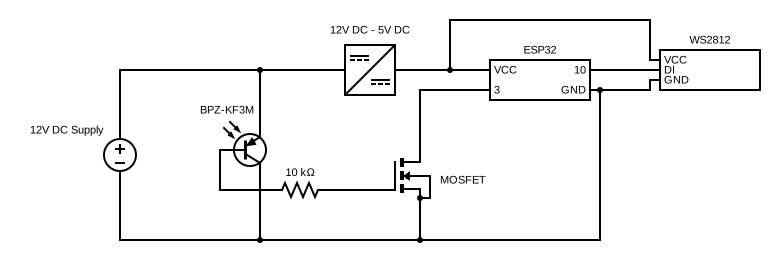
Using agentic assistants to work out how to couple all of the bits together was really useful. I didn’t have a level shifter to get the sensor’s 12 V output safely to the ESP32’s 3v3 GPIO, but I did have a MOSFET. I used it as a switch: the sensor output drives the gate through a 10 kΩ resistor, while the source is connected to ground and the drain to GPIO3. With INPUT_PULLUP enabled, the MOSFET pulls GPIO3 low when it switches on. The resistor is in series with the gate; the MOSFET keeps the sensor’s 12 V signal off the ESP32 pin.

Circuit diagram for the Parking Assist sensor, ESP32, MOSFET, buck converter and LED ring

The ESPHome configuration is split into a small device file and a package for the parking behavior. The device file supplies the pin and timing values; the package defines the ring, beam sensor, and scripts. Here are the parts that make the idle delay behave differently from a re-break during an active parking cycle:

substitutions:
  ring_pin: GPIO10
  beam_pin: GPIO3
  clear_timeout: 60s
  break_delay: 4s

globals:
  - id: g_active
    type: bool
    restore_value: no
    initial_value: 'false'
  - id: g_doorway_blocked
    type: bool
    restore_value: no
    initial_value: 'false'

script:
  - id: beam_break_handler
    mode: restart
    then:
      - if:
          condition:
            lambda: 'return !id(g_active);'
          then:
            - delay: ${break_delay}
      - if:
          condition:
            binary_sensor.is_on: beam_raw
          then:
            - globals.set:
                id: g_active
                value: 'true'
            - globals.set:
                id: g_doorway_blocked
                value: 'true'
            - light.turn_on:
                id: ring
                brightness: 0.6
                effect: Red Chaser

binary_sensor:
  - platform: gpio
    id: beam_raw
    internal: true
    pin:
      number: ${beam_pin}
      mode: INPUT_PULLUP
    filters:
      - delayed_off: 100ms
    on_press:
      - script.stop: green_flash_then_on
      - script.execute: beam_break_handler
    on_release:
      - if:
          condition:
            lambda: 'return id(g_active);'
          then:
            - script.stop: beam_break_handler
            - script.execute: green_flash_then_on

The g_active check decides whether to wait. After an idle wait, the second check confirms the beam is still blocked before setting the blocked state or starting the red chaser. If it cleared during those four seconds, nothing is shown. During an active cycle, that wait is skipped, so a re-break still turns the ring red immediately. The complete package also handles the green flashes and timeout. I’ve also got an additional binary sensor exposed to Home Assistant, but that’s for diagnostic purposes only.

Hacking the DETA rewireable plug

There are a bunch of inexpensive IoT devices coming onto the market. One of these ranges are the GridConnect devices available from Bunnings. I’ve been eyeing these off, because they include some fairly reasonable looking switches and plugs, and, most importantly, are legal to have installed in your home in Australia.

I’m not okay with sticking a bunch of devices into my home network that communicate with the outside world. I like to use Apple’s HomeKit, which means the communication is funnelled through their systems, and everything I have configured as a HomeKit accessory either has no cloud component, and is where possible isolated onto a seperate wireless network.

In fact, most of my devices are home built, and have limited accesibility: they are permitted to connect to an MQTT server and nothing else.

Most of the commercially available items in Australia fail this test: they all have their own little cloud service. I dislike this for a couple of reasons: the first is security and privacy. I don’t trust that these providers will protect my data.

The second is a little more subtle: if an IoT provider goes out of business (or decides to end-of-life some products), then you are no longer able to access them in the way you might have liked.

So, I’ve been creating my own devices, or re-purposing commercial devices where possible. I grabbed a couple of the Mirabella globes, and was able to flash them with an ESPHome firmware, that I believe hardens the device somewhat. Having controllable light globes is neat, but realistically, they are of limited use. Having to use an App to turn on and off your lights is unacceptable, but also so is having an always listening microphone. And, again, what happens when you want to turn your lights on and your internet is down?

So, I’m more interested in smart switches.

I was not able to find much information about the Deta line of products that support GridConnect, so I went and bought the cheapest one, that I thought I was going to be realistically able to reverse engineer.

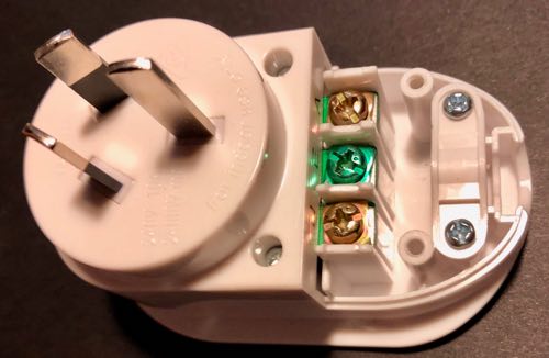
Opening up the “user accessible” region, we see the three screws for attaching the cable, and some lovely 2.0mm triangular screws.

IMG 2119

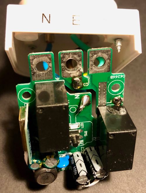
After spending more money on a set of screwdriver bits that had this size and shape, we are able to see the top of the PCB.

IMG 2120

Note that there are two relays: this is safer than things like the Sonoff Basic, that only switch the active wire, rather than both.

The underneath shows clearly the separation between the different AC lines.

IMG 2121

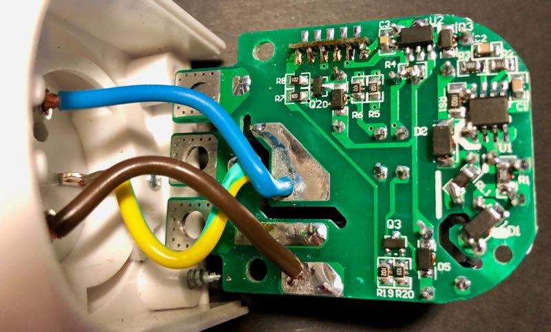
Finally, we can see the brains behind this switch:

IMG 2122

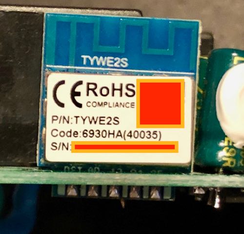
Note the code on the microcontroller: TYWE2S. Plugging that into a search engine yielded some interesting results.

It turns out that not only are these using an ESP8285 (which is just an ESP8266 with onboard flash, and in a smaller package), but they are running the Tuya firmware. So, it wasn’t even necessary to have opened up the casing.

Since I had a Raspberry Pi Zero W configured to run tuya-convert, I built up a simple firmware that would enable me to run OTA updates after flashing, and settled down to working out which GPIO pins are attached to which parts: the button, LED and relay.

(Oh, and this was interesting: both the active and neutral lines are toggled by relays, as opposed to something like the Sonoff, that only toggles the active line).

At some point, possibly because I was tired, I flashed a firmware that accessed GPIO pins 6 and 7. This locks the device up, and prevents booting. So, I then soldered some wires onto the device (after opening it back up again: so it turned out I did need that fancy screwdriver bit) to get access to the UART.

Interestingly, the ESPHome firmware detects that it’s been unable to boot, and boots into a safe mode. So, again, in hindsight, I still didn’t need to open it up.

Through trial and error, I was able to determine which GPIO was the button. That’s the easiest (and was helpful for me to be able to determine the LED and relay).

Surprisingly, it was GPIO1. Those familiar with the ESP8266 may know this is normally the TX pin for the UART. Which explains why, when I had the serial port connected, I was seeing a bunch of weird things when I pushed the button.

Once I had that, it was a matter of trying each GPIO in turn to see which was the relay and which was the LED. I did them in pairs, and happened to choose GPIO13 and GPIO14 in the same test, so for a while I thought maybe the relay and the LED were hardwired together.

Anyway, I now have a working firmware for this device:

substitutions:
  device_name: deta_plug

wifi:
  # Hah!

esphome:
  name: $device_name
  platform: ESP8266
  board: esp01_1m

binary_sensor:
  - platform: status
    name: "Status"

  - platform: gpio
    pin:
      number: GPIO1
      inverted: true
      mode: INPUT_PULLUP
    name: GPIO1
    on_press:
      - switch.toggle: relay

switch:
  - platform: gpio
    id: led
    pin:
      number: GPIO13
      inverted: true
  - platform: gpio
    id: relay
    pin: GPIO14
    on_turn_on:
      - switch.turn_on: led
      - mqtt.publish:
          topic: HomeKit/${device_name}/Switch/On
          retain: ON
          payload: 1
    on_turn_off:
      - switch.turn_off: led
      - mqtt.publish:
         topic: HomeKit/${device_name}/Switch/On
         retain: ON
         payload: 0


sensor:
  - platform: wifi_signal
    name: "WiFi signal sensor"
    update_interval: 60s

ota:

logger:

mqtt:
  broker: "mqtt.lan"
  discovery: false
  topic_prefix: esphome/${device_name}
  on_message:
    - topic: HomeKit/${device_name}/Switch/On
      payload: "1"
      then:
        - switch.turn_on:
            id: relay
    - topic: HomeKit/${device_name}/Switch/On
      payload: "0"
      then:
        - switch.turn_off:
            id: relay

I’m using my MQTT ⟺ HomeKit bridge, since that works great, but you could easily change the MQTT topics, or do whatever else you want to do.

Update: turns out, I just needed to search for the code: this page has everything I would have needed.

Sonoff Basic unable to connect to Wifi on AC power

I have a few of the Sonoff Basic devices. I’d flashed one of them with a custom firmware before, but then was using the stock firmware, and having them operate in LAN mode.

However, that’s less than awesome: for one, it means I need to have (and maintain) a custom service running somewhere on my network, and because of the way you need to provision them, it’s hard to move this to a different machine.

With ESPhome, I’ve started re-flashing my old ESP8266 devices, so I had a go at some of the Sonoff. Neither of the ones I had installed (with the stock firwmare) had headers soldered onto the UART pins, but it turned out that one of my USB-UART devices had the pins in the correct order that I was able to (after disconnecting it from the mains, of course), hold the button down, press the USB-UART device into position, and then connect the USB port. After a couple of seconds, I released the button, and, eventually (after a couple of tries), have the device in “flash” mode.

Of course, I only discovered this after totally disconnecting one, soldering on some header pins and then connecting the device using hookup wires.

Then I uploaded the custom firmware. At which point I was able to re-upload firmware using the OTA mode, which means I no longer had to juggle the serial connector, USB and GPIO0 button.

So, I then flashed another one, this time without having to solder, and had both of them configured as devices on my IoT network.

But, there was a problem. They would only connect to the Wifi when they were connected to the serial connector. When I disconnected the serial port, and reconnected them to the mains supply, they would operate correctly, but would not connect to Wifi. Even though one of them was literally less than a metre from the router.

I did a bit of research, and there apparently are a batch that are like this. Tasmota firmware has issues that mention this on GitHub, but then in those issues they are marked as “resolved”. Unfortunately there was not really a good resolution - more than likely it was just some type of stale-bot just closing issues that had not been updated in a certain time frame. At least one of these suggested that a newer firmware worked, but that was no good for me.

A couple of these issues identified that there was a missing capacitor, but one of them mentioned that they had soldered together the 3v3 supply, and the RX and TX pins.

So, I ran some experiments. Connecting the 3v3 pin to either of those other pins had no effect, but connecting the RX and TX together suddenly allowed my device with the header pins to connect!

Luckily, these pins are adjacent, so I found a jumper (I remember when these were on just about every hard drive, but I couldn’t find one today with a single pin), and hooked it up.

All good!

Unfortunately, when putting it back together I didn’t align the top cover with the button correctly, so I managed to break that. Which just means I can’t control the switch directly, only remotely. That’s pretty annoying (it’s one of the reasons I went with Sonoff over some other solutions), but at least it works on HomeKit now.

iPad Thumbscanner

Well, my iPad 2 arrived yesterday. Loving it.

But that’s not what this post is about.

At work, one of our products is a thumbscanner system. I was discussing with our CEO the other day how the best way to have this in a unit was, and ideally an iPad or other tablet would be best.

The issue with the iPad is that you cannot just connect any hardware to it.

But then I remembered how some people had connected all types of USB hardware, including in one case a USB-ADB adaptor and an old, old keyboard. All you need is one of the iPad Camera Connection Kit thingos.

Guess I’ll have to get one of those, and see what I can manage to get it to do…

…The trigger for thinking about this: Oscium’s iMSO-104 turns your iPad into a mixed signal oscilloscope

WOOT!

I seriously, seriously Want One Of These:

51dmPeiGT2L.SL500_AA280.jpg

(via Twitter @fraserspeirs, available from Amazon)

Running monitors at higher resolution.

Most monitors seem to be able to be driven at a higher resolution than it says they can. In some cases, the higher resolution gives a better picture, in other cases it doesn’t.

My work just bought me a new LG W1942T, which is rated as running at 1400x900, which for a 19" monitor isn’t that high. My laptop (15") does the same resolution. It’s possible to run the W1942T at 1680x1050, but I really don’t know if the blurriness is caused by that, or if it just isn’t the best monitor available.

My boss bought a 22" LG monitor, which is rated at 1680x1050, but it does 2048x1280 quite comfortably. And I have an nice old Dell E172FP, which looks best at 1344x1074, rather than the 1280x1024 which it says it can do.

Repeat. Rinse.

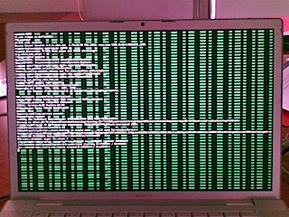
After my last post, I has kinda bummed when the same thing happened again. Luckily, the same process fixed it, but I really don’t know why it occurred to begin with. I think the same fault was fixed by fsck, so that might have something to do with it.

Anyway, I took some snaps this time.

16092008.jpg

I wasn’t able to take a shot of the initial boot screen (ironically, it caused my phone to crash. Twice).

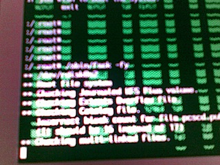
16092008(001).jpg

This second one shows how the text is now overwriting the green corruption. Sorry about the blurriness, but if you look carefully you may notice that the file with the incorrect block count is pcscd.pub, or something. This appears to be the file /var/run/pcscd.run, but I don’t really know what this does.

Mac Mini Media Machine

Well, I’ve bit the bullet and bought a Mac Mini Core Duo to use as my media centre. The old Xbox just doesn’t cut it anymore - the two things I need to be able to do are play H.264 movies, and record video from Digital TV, and it can’t do either of these. I’ve had to purchase an eyeTV USB TV Tuner to do the latter (and I’ll be returning my Miglia TVmini2, since it doesn’t do what it is advertised to do - which is play Digital TV properly, or do scheduled recording properly).

The machine was ordered online via the Apple Store. I’ve had issues with NextByte in the past, so I was a bit loathe to purchase through them. I rang them anyway, figuring that if they had one in store, I could order it, and collect it the same day.

They didn’t and said that they had about 6 on order, and there weren’t any in Australia.

Now, I knew that wasn’t the case, as Apple have a 24 hour shipping note on this model. So, it was “no thanks” to their offer to place an order. And I ordered online.

Within about 5 hours, my order had shipped. And, for evidence that it has been shipped, TNT have the following data about my package:

So, I’m all excited. My new machine is supposed to arrive tomorrow…

xkcd Success

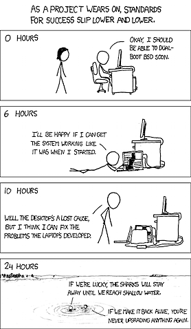
Ah, I’ve been there. Mine was dual-booting OS X onto an unsupported Dell PC. I had a second Hard Disk that I was putting it onto, yet somehow I managed to screw up the Windows partition as well. Luckily I didn’t destroy the laptop. And I never got near the sharks…

And, yet another plug for xkcd.com - if you haven’t subscribed to his RSS feed, then you really should.

Review: miglia TVmini<sup>2</sup>/equinox The Tube

I lashed out yesterday, and bought something that I’ve been wanting for a while.

A USB TV Tuner stick.

I went for the miglia TVmini2, as it was (I thought) fairly inexpensive. I’m not sure I made the right decision right now.

For starters, it doesn’t actually come with the software. Sure, it’s got a CD with some demo software of other stuff, but the actual software (which is actually written by another company, called equinox), The Tube, needs to be downloaded from the internet before installation.

Which wouldn’t be too bad, but it’s a 104Mb download. Which meant I couldn’t (a) start playing with it as soon as I bought it, since I was in town, and not near a free wireless point, and (b) start playing with it as soon as I got home, since it took about 30 minutes to grab.

It gets worse, though. Even though the software really requires a dongle (the USB tuner is really just a dongle, after all), the manufacturers insist that you register the software, using the included key string. And it only works on one machine without de-registration, apparently. Which kind of sucks, because I’d like to have it moved between more than one machine.

The hardware itself seems okay. I haven’t been able to make it work with any other software yet. I’ve tried a couple of downloads, but they wouldn’t recognise it.

System Profiler reports the device as looking like:

TVMini2:

Version: 1.00

Bus Power (mA): 500

Speed: Up to 480 Mb/sec

Manufacturer: Miglia

Product ID: 0x0069

Serial Number: 0000000001

Vendor ID: 0x18f3

The software, on the other hand, seems to have some good features, but quite a few flaws.

The manufacturers have decided to make the application scriptable. This is a very good thing, as it will allow me to, for instance, set up Salling Clicker to be able to control it. Which will be very good. I’d also be able to make a rudimentary controller for network or local remote control. Which I may do: more on that later.

Another good feature is the simplicity of the software. The basic window is shown below.
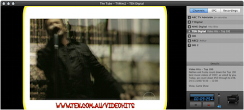
You basically have a video section, with a controller on the right. This appears to be fixed. Although you can hide the main video area, they resize together. Which is a bad thing, if you like to resize the video to a small size while you write a review of something, for instance. Like I’d like to do now. It means that the controller becomes fairly unusable fairly quickly:
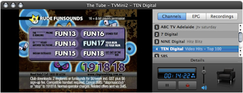
This is as small as the remote area gets. Any further resizing just shrinks the video display in that window. You can hide the Details area (this is shown above), but you can’t hide the record area.

You can hide the remote, too. This makes shrinking the video a bit more usable:
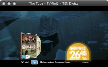
I anticipate being able to build another controller that floats, and can be used in conjunction with the view shown above. More below on some issues that might appear with this, when I discuss the AppleScript interface in a bit of detail.

The controller itself is mostly okay. The main/default view has a list of channels. This is customisable. You can scan for channels, and then delete the ones you don’t watch, and rename the ones you do. Scanning takes a long time, and is probably worth re-doing every now and then, just in case a new station has been added.
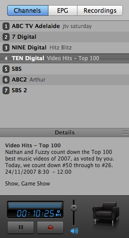
The bottom area of the controller is the recording pane. You can pause live TV, record the current stream, and if you have been watching a channel for a little while, skip back through the already viewed stuff. I did a quick test where I watched for a while, then went back to try to record a section from the past. The program developed a spinning beach ball, and I had to Force Quit. I’ll continue to test it again later, as this is a nice feature.

There’s also a button link to their other software, MediaCentral, which totes itself as a total replacement for FrontRow. And, I’ve had a bit of a look at it. It looks pretty good, actually. May be worth investing in, and using this on the Mac Mini when I finally get it, and set it up as my Media Centre. (Typing Central reminds me to just let all of the yanks out there know the correct way to spell centre. Yank is a slang term Australians use to refer to Americans).

If you record live TV, it stores it in the recordings pane.
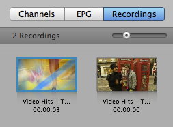
You can then export from here, in order to be able to view on another device, or in another program. It exports raw DV fairly quickly (almost real time, I think, perhaps even faster), but as expected exporting to m4v takes a bit longer. It appears that these are the only formats it will export: iPod, iPhone and AppleTV are all m4v, and iMovie is DV. I’m still going to record some stuff and see what the quality is like. Gotta wait for some decent content first.

Which brings me nicely to the next topic. Electronic Program Guide and Scheduled Recording. The interface is, again, fairly simple. All programs appear in the one list, there doesn’t appear to be a method of filtering so sort by channels. You can search or filter by title and description. To schedule a recording, simply click the black dot next to the program time.
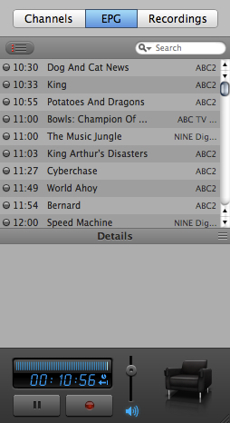
Clicking on a title will show the details about that program. This is obtained from the digital TV data stream, although it is possible to add in an external TV guide, using the open XMLTV standard. Unfortunately, there doesn’t seem to be a way to subscribe to an XML feed. EPG via RSS, that would be awesome.

If you click on the “Show Recordings” button, it will filter to only display the programs you have scheduled to record. You can then de-select them by re-clicking the red dot. Fairly easy to understand. It also seems to have some smarts about overlapping programs, and will display a different coloured dot when they clash.
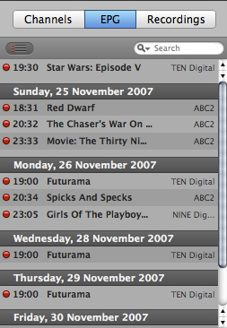
Okay, feature list is pretty much done. What doesn’t it do, or what does it do badly?

AppleScript support.

You can do quite a few things with AppleScript, such as pause, play, start recording and so on. It appears that you cannot get decent data from the EPG, for instance. So I can’t build a fully replacement EPG in another application, unless I access the data directly from the file. This file is stored as an SQLite database. So I should be able to grep data out of this using the relevant tools. This seems to be an oversight, since you can schedule recordings, and access the EPG data, but I can’t figure out how to get meaningful data from the EPG. This would be a necessity for a proper Salling Clicker interface, that allowed me to just run the program in full-screen mode and only use the phone for the remote, doing all of the programming with that instead.

You can also export from AppleScript. Not sure if you can choose to export DV, which I would probably want to do. So I can post-process the data and remove advertisements, for instance. But I cannot find a way to choose a channel by channel name. Which would be useful for a remote program, either on phone or computer.

Possibly the biggest annoyance: in every instance I have seen, this application is called The Tube. But to access it in AppleScript, you need to use TheTube. Why do this? You can have spaces in application names in AppleScript and it works fine.

Data file formats.

The channel data is stored as an XML/plist file. Which is a good thing. You can hand-tweak this file, which is much faster than, and less error-prone than deleting them inside the software. Especially since right-clicking to delete doesn’t actually select the channel, so the previously selected channel gets deleted instead.

Scheduled programs are also plist files. You could create these files with another piece of software, and just rely on The Tube to record them. I haven’t tried creating a file and seeing if it automatically records, or whether you need to start/re-start The Tube to get it to notice. Still on the TODO list.

The video data is stored in a package. There are a couple of TIFFs, for preview purposes, but these aren’t always the correct aspect ration. In fact, since most of my Digital TV seems to be broadcast in 16:9, with black bars on the sides, this is always the wrong aspect ratio as these TIFFs are all 4:3.

Bonus points if you can name the song and artist this preview is from!

Inside the package is a plist file with data about the recording. But the actual data is stored in two files, Media.tvi and Media.tvm. I’m still trying to find out what file format these are - VLC doesn’t seem to recognise them, although I suspect they are a standard file format, just hidden. I’d like to be able to get this data without necessarily having to use The Tube. According to one website, this data is just the raw MPEG stream. Changing the file extension to .mpg or .mpeg doesn’t allow for playback Might need more research.