Hacking Arlec's 'Smart' sensor light

Quite some time ago, I purchased one of the Arlec Smart Security Lights from Bunnings. The big draw for me was that these devices have an ESP8266, and run a Tuya firmware, which can be trivially flashed without opening up the unit.

In this case, though, the device was not really that capable. Whilst there is a PIR sensor (and an LDR for tuning if the light should turn on yet or not), the status of the PIR is not exposed at all. Instead, the firmware allows toggling between three states: “ON”, “OFF”, and “SENSOR”.

That’s not actually that useful. For one, it makes using it in conjunction with a physical switch really inconvenient. The behaviour I would prefer is:

  • Light ON/OFF state can be toggled by network request.
  • Light ON/OFF state can be toggled by physical switch. It must not matter which state the switch is in, toggling it must toggle the light.
  • PIR ON turns ON the light.
  • PIR OFF turns OFF the light, but only if it was turned ON by PIR.

As the last point indicates, the only time the PIR turning off should turn the light off is if the light was turned on by the PIR. That is, either physical switch actuation or a network request should turn the light into manual override ON.

There is no manual override OFF.

Most of this was already present in a firmware I wrote for adding a PIR to a light strip. However, the ability to also toggle the state using a physical switch is important to me: not in the least because there is a switch inside the door where I want to mount this, and I’m very likely to accidentally turn it on when I go outside: it’s also a much better solution to a manual override than just having to use HomeKit. I’ll possibly add that feature back into the aforementioned project.

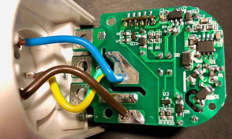
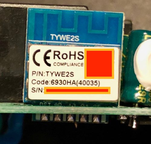
Like all of the other Grid Connect hardware I’ve used so far, it was easy to flash using tuya convert. But I did run into a bunch of problems from that point onwards. The base contains the ESP8266, one of the TYWE2S units, and it’s possible to see without opening up the sensor unit that this has three GPIO pins connected: GPIO4, GPIO5 and GPIO12.

With a custom firmware, it was possible to see that GPIO5 is connected to the green LED near the PIR sensor, but the other two appear to be connected to another IC on the PCB. I thought perhaps this could be accessed using the TuyaMCU protocol, but had no luck.

As it turns out, I’d prefer not to have to use that. There are two more wires, it would be great if I could connect one of them to the relay, and the other to the PIR.

Indeed, with limited rewiring (I did have to cut some tracks and run wires elsewhere), I was able to connect GPIO12 to the point on the PCB that the output from the other IC that triggered the relay, and GPIO4 to the input of the IC that was sensing the PIR output.

I also ran an extra pair of wires from GPIO14 and GND, to use to connect to the physical switch. These will only transmit low voltage.

Unfortunately, I forgot to take photos before putting it all back together and having it mounted on the wall.

Then we just need the firmware:

esphome:
  name: $device_name
  platform: ESP8266
  board: esp01_1m

globals:
  - id: manual_override
    type: bool
    restore_value: no
    initial_value: 'false'
  - id: mqtt_triggered
    type: bool
    restore_value: no
    initial_value: 'false'

sensor:
  - platform: wifi_signal
    name: "WiFi signal sensor"
    update_interval: 60s

binary_sensor:
  - platform: gpio
    pin: GPIO4
    id: pir
    device_class: motion
    filters:
      - delayed_off: 15s
    on_press:
      - light.turn_on: green_led
      - mqtt.publish:
          topic: HomeKit/${device_name}/MotionSensor/MotionDetected
          payload: "1"
      - switch.turn_on: relay
    on_release:
      - light.turn_off: green_led
      - mqtt.publish:
          topic: HomeKit/${device_name}/MotionSensor/MotionDetected
          payload: "0"
      - if:
          condition:
            lambda: 'return id(manual_override);'
          then:
            logger.log: "Manual override prevents auto off."
          else:
            switch.turn_off: relay

  - platform: gpio
    pin:
      number: GPIO14
      mode: INPUT_PULLUP
    name: "Toggle switch"
    filters:
      - delayed_on_off: 100ms
    on_state:
      - switch.toggle: relay
      - globals.set:
          id: manual_override
          value: !lambda "return id(relay).state;"

ota:

logger:

output:
  - platform: esp8266_pwm
    id: gpio5
    pin:
      number: GPIO5
    inverted: False

switch:
  - platform: gpio
    id: relay
    pin:
      number: GPIO12
      # inverted: True
      # mode: INPUT_PULLDOWN_16
    on_turn_on:
      - if:
          condition:
            lambda: 'return id(mqtt_triggered);'
          then:
            logger.log: "No MQTT message sent"
          else:
            mqtt.publish:
              topic: HomeKit/${device_name}/Lightbulb/On
              retain: ON
              payload: "1"
    on_turn_off:
      - if:
          condition:
            lambda: 'return id(mqtt_triggered);'
          then:
            logger.log: "No MQTT message sent"
          else:
            mqtt.publish:
              topic: HomeKit/${device_name}/Lightbulb/On
              retain: ON
              payload: "0"


light:
  - platform: monochromatic
    id: green_led
    output: gpio5
    restore_mode: ALWAYS_OFF
    default_transition_length: 100ms

mqtt:
  broker: "mqtt.lan"
  discovery: false
  topic_prefix: esphome/${device_name}
  on_message:
    - topic: HomeKit/${device_name}/Lightbulb/On
      payload: "1"
      then:
        - globals.set:
            id: mqtt_triggered
            value: 'true'
        - switch.turn_on: relay
        - globals.set:
            id: mqtt_triggered
            value: 'false'
        - globals.set:
            id: manual_override
            value: !lambda "return !id(pir).state;"
    - topic:  HomeKit/${device_name}/Lightbulb/On
      payload: "0"
      then:
        - globals.set:
            id: mqtt_triggered
            value: 'true'
        - switch.turn_off: relay
        - globals.set:
            id: manual_override
            value: 'false'
        - globals.set:
            id: mqtt_triggered
            value: 'false'

I’ve also implemented a filter on sending the state to MQTT: basically, we don’t want to send a message to MQTT if we received the same message. There is a race condition that can occur where this results in fast toggling of the relay as each toggle sends a message, but then receives a message with the alternate state. I’ve had this on my Sonoff Mini firmware too.
Arlec Powerboard esphome

I bought one of the Grid Connect powerboards from Bunnings last week, and flashed it with a custom firmware.

The model I bought was the PB89HA, which is the one with 5 sockets (one of which is not switchable).

The button is on GPIO3, and the LED is an inverted GPIO1.

The four relays are on GPIO5, GPIO4, GPIO13 and GPIO12, starting with the one closest to the button.

Since there is only one button, and four switchable outlets, I had to come up with a mechanism for controlling all of them. I ended up (after playing around with single-through-quadruple click) with a single click for toggling the first relay (nearest the button). Then, a medium (between 1 and 2 second) press turns all relays off, and a long (greater than 2 second) press turns them all on.

This is not really ideal, as there is no way to toggle just relay 2-4 without using some sort of external control - which goes against my ethos with respect to smart home.

Having said that, I’m not actually sure how I’m going to use this board…I don’t really have a bunch of things that are potentially close together that need individual control. I guess I could have it turn off everything in the entertainment unit except the PVR - that might be a way to save power overnight. I’d want the button more accessible than the powerboard that currently controls them though.

Anyway, the base YAML file follows - be aware that this does not include wifi, and would need to be included in an actual config file (with a device name defined).

esphome:
  name: $device_name
  platform: ESP8266
  board: esp01_1m
  on_boot:
    - light.turn_on:
        id: led
        brightness: 20%

binary_sensor:
  - platform: status
    name: "Status"

  - platform: gpio
    pin:
      number: GPIO3
      inverted: true
      mode: INPUT_PULLUP
    name: button
    on_multi_click:
      - timing:
        - ON for at least 1s
        - OFF for at least 0.2s
        then:
          - switch.turn_off: relay_0
          - switch.turn_off: relay_1
          - switch.turn_off: relay_2
          - switch.turn_off: relay_3

      - timing:
        - ON for at least 2s
        - OFF for at least 0.2s
        then:
          - switch.turn_on: relay_0
          - switch.turn_on: relay_1
          - switch.turn_on: relay_2
          - switch.turn_on: relay_3

      - timing:
        - ON for at most 0.5s
        - OFF for at least 0.2s
        then:
          - switch.toggle: relay_0

switch:
  - platform: gpio
    id: relay_0
    pin: GPIO5
    on_turn_on:
      - mqtt.publish:
          topic: HomeKit/${device_name}/Outlet/0/On
          retain: ON
          payload: 1
    on_turn_off:
      - mqtt.publish:
         topic: HomeKit/${device_name}/Outlet/0/On
         retain: ON
         payload: 0

  - platform: gpio
    id: relay_1
    pin: GPIO4
    on_turn_on:
      - mqtt.publish:
          topic: HomeKit/${device_name}/Outlet/1/On
          retain: ON
          payload: 1
    on_turn_off:
      - mqtt.publish:
         topic: HomeKit/${device_name}/Outlet/1/On
         retain: ON
         payload: 0

  - platform: gpio
    id: relay_2
    pin: GPIO13
    on_turn_on:
      - mqtt.publish:
          topic: HomeKit/${device_name}/Outlet/2/On
          retain: ON
          payload: 1
    on_turn_off:
      - mqtt.publish:
         topic: HomeKit/${device_name}/Outlet/2/On
         retain: ON
         payload: 0

  - platform: gpio
    id: relay_3
    pin: GPIO12
    on_turn_on:
      - mqtt.publish:
          topic: HomeKit/${device_name}/Outlet/3/On
          retain: ON
          payload: 1
    on_turn_off:
      - mqtt.publish:
         topic: HomeKit/${device_name}/Outlet/3/On
         retain: ON
         payload: 0

light:
  - platform: monochromatic
    output: led1
    id: led
    restore_mode: ALWAYS_ON

output:
  - platform: esp8266_pwm
    pin:
      number: GPIO1
    id: led1
    inverted: True

sensor:
  - platform: wifi_signal
    name: "WiFi signal sensor"
    update_interval: 5min

ota:

logger:

mqtt:
  broker: "mqtt.lan"
  discovery: false
  topic_prefix: esphome/${device_name}
  on_message:
    - topic: HomeKit/${device_name}/Outlet/0/On
      payload: "1"
      then:
        - switch.turn_on:
            id: relay_0
    - topic: HomeKit/${device_name}/Outlet/0/On
      payload: "0"
      then:
        - switch.turn_off:
            id: relay_0

    - topic: HomeKit/${device_name}/Outlet/1/On
      payload: "1"
      then:
        - switch.turn_on:
            id: relay_1
    - topic: HomeKit/${device_name}/Outlet/1/On
      payload: "0"
      then:
        - switch.turn_off:
            id: relay_1

    - topic: HomeKit/${device_name}/Outlet/2/On
      payload: "1"
      then:
        - switch.turn_on:
            id: relay_2
    - topic: HomeKit/${device_name}/Outlet/2/On
      payload: "0"
      then:
        - switch.turn_off:
            id: relay_2

    - topic: HomeKit/${device_name}/Outlet/3/On
      payload: "1"
      then:
        - switch.turn_on:
            id: relay_3
    - topic: HomeKit/${device_name}/Outlet/3/On
      payload: "0"
      then:
        - switch.turn_off:
            id: relay_3

Hacking the DETA rewireable plug

There are a bunch of inexpensive IoT devices coming onto the market. One of these ranges are the GridConnect devices available from Bunnings. I’ve been eyeing these off, because they include some fairly reasonable looking switches and plugs, and, most importantly, are legal to have installed in your home in Australia.

I’m not okay with sticking a bunch of devices into my home network that communicate with the outside world. I like to use Apple’s HomeKit, which means the communication is funnelled through their systems, and everything I have configured as a HomeKit accessory either has no cloud component, and is where possible isolated onto a seperate wireless network.

In fact, most of my devices are home built, and have limited accesibility: they are permitted to connect to an MQTT server and nothing else.

Most of the commercially available items in Australia fail this test: they all have their own little cloud service. I dislike this for a couple of reasons: the first is security and privacy. I don’t trust that these providers will protect my data.

The second is a little more subtle: if an IoT provider goes out of business (or decides to end-of-life some products), then you are no longer able to access them in the way you might have liked.

So, I’ve been creating my own devices, or re-purposing commercial devices where possible. I grabbed a couple of the Mirabella globes, and was able to flash them with an ESPHome firmware, that I believe hardens the device somewhat. Having controllable light globes is neat, but realistically, they are of limited use. Having to use an App to turn on and off your lights is unacceptable, but also so is having an always listening microphone. And, again, what happens when you want to turn your lights on and your internet is down?

So, I’m more interested in smart switches.

I was not able to find much information about the Deta line of products that support GridConnect, so I went and bought the cheapest one, that I thought I was going to be realistically able to reverse engineer.

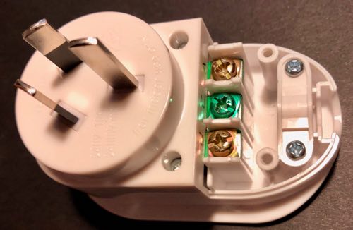
Opening up the “user accessible” region, we see the three screws for attaching the cable, and some lovely 2.0mm triangular screws.

IMG 2119

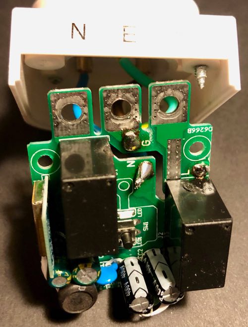
After spending more money on a set of screwdriver bits that had this size and shape, we are able to see the top of the PCB.

IMG 2120

Note that there are two relays: this is safer than things like the Sonoff Basic, that only switch the active wire, rather than both.

The underneath shows clearly the separation between the different AC lines.

IMG 2121

Finally, we can see the brains behind this switch:

IMG 2122

Note the code on the microcontroller: TYWE2S. Plugging that into a search engine yielded some interesting results.

It turns out that not only are these using an ESP8285 (which is just an ESP8266 with onboard flash, and in a smaller package), but they are running the Tuya firmware. So, it wasn’t even necessary to have opened up the casing.

Since I had a Raspberry Pi Zero W configured to run tuya-convert, I built up a simple firmware that would enable me to run OTA updates after flashing, and settled down to working out which GPIO pins are attached to which parts: the button, LED and relay.

(Oh, and this was interesting: both the active and neutral lines are toggled by relays, as opposed to something like the Sonoff, that only toggles the active line).

At some point, possibly because I was tired, I flashed a firmware that accessed GPIO pins 6 and 7. This locks the device up, and prevents booting. So, I then soldered some wires onto the device (after opening it back up again: so it turned out I did need that fancy screwdriver bit) to get access to the UART.

Interestingly, the ESPHome firmware detects that it’s been unable to boot, and boots into a safe mode. So, again, in hindsight, I still didn’t need to open it up.

Through trial and error, I was able to determine which GPIO was the button. That’s the easiest (and was helpful for me to be able to determine the LED and relay).

Surprisingly, it was GPIO1. Those familiar with the ESP8266 may know this is normally the TX pin for the UART. Which explains why, when I had the serial port connected, I was seeing a bunch of weird things when I pushed the button.

Once I had that, it was a matter of trying each GPIO in turn to see which was the relay and which was the LED. I did them in pairs, and happened to choose GPIO13 and GPIO14 in the same test, so for a while I thought maybe the relay and the LED were hardwired together.

Anyway, I now have a working firmware for this device:

substitutions:
  device_name: deta_plug

wifi:
  # Hah!

esphome:
  name: $device_name
  platform: ESP8266
  board: esp01_1m

binary_sensor:
  - platform: status
    name: "Status"

  - platform: gpio
    pin:
      number: GPIO1
      inverted: true
      mode: INPUT_PULLUP
    name: GPIO1
    on_press:
      - switch.toggle: relay

switch:
  - platform: gpio
    id: led
    pin:
      number: GPIO13
      inverted: true
  - platform: gpio
    id: relay
    pin: GPIO14
    on_turn_on:
      - switch.turn_on: led
      - mqtt.publish:
          topic: HomeKit/${device_name}/Switch/On
          retain: ON
          payload: 1
    on_turn_off:
      - switch.turn_off: led
      - mqtt.publish:
         topic: HomeKit/${device_name}/Switch/On
         retain: ON
         payload: 0


sensor:
  - platform: wifi_signal
    name: "WiFi signal sensor"
    update_interval: 60s

ota:

logger:

mqtt:
  broker: "mqtt.lan"
  discovery: false
  topic_prefix: esphome/${device_name}
  on_message:
    - topic: HomeKit/${device_name}/Switch/On
      payload: "1"
      then:
        - switch.turn_on:
            id: relay
    - topic: HomeKit/${device_name}/Switch/On
      payload: "0"
      then:
        - switch.turn_off:
            id: relay

I’m using my MQTT ⟺ HomeKit bridge, since that works great, but you could easily change the MQTT topics, or do whatever else you want to do.

Update: turns out, I just needed to search for the code: this page has everything I would have needed.